The Sunkko range of spot welders are low cost, hence popular, spot welders for constructing rechargeable battery packs. They are manufactured by Meilidee Electronics Co. Ltd. an unknown Chinese company.
Many users have reported problems of reliability. The internet has multiple forums asking about how various models can be repaired but the only practical repair articles found involve replacing blown triacs then making simple circuit additions – heatsinks, current limiters, etc.
Because of their low cost, and despite reported failures and lack of repair information available, the Sunkko units are very popular with hobbyists who make battery packs for RC models, e-bikes, home built power walls, etc.
Background to Repair
I occasionally volunteer at a local recycling group that disassembles e-waste into their component materials – metal, plastic, circuit boards which are then on sold to material recyclers. The group also undertake low volume manufacture of custom electronic designs that can utilize some special components derived from the disassembled electronic equipment. The most common reused component are 18650 Li-Ion batteries from faulty laptop battery packs.
Battery packs are disassembled and the failed cells identified. The remaining potentially reusable cells are tested and graded. The higher grade cells are then rebuilt into battery packs which are used in a number of the designs.
The group therefore has a number of battery spot welders, all from Sunkko, in regular use. In service these units generally only last a year or two before they fail. Faulty units are replaced as repair attempts had been invariably unsuccessful.
Given that there was now a collection of failed units I decided it was worth the time to investigate the causes of failures and so reduce the expenditure on new units. Different models from Sunkko have been purchased over time but the most common is the 709A. This is also the model most frequently mentioned in web comments.
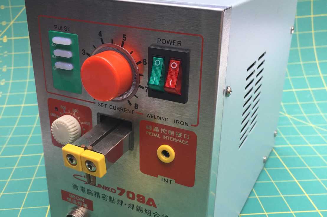
Sunkko 709A

Opening the unit what is found is a large power transformer and incoming AC power lead and fuse, a spring loaded mechanism to trigger and convey the high current welding pulses to the pair of welding electrodes, and a single circuit board mounted behind the front panel of the unit.
The spring loaded welding arms assembly passes through a square cut-out in the circuit board. To the left of the cut-out are 2 wires going to a temperature switch. This is installed in thermal contact with the power transformer’s winding. This safety device would stop the current pulses if the power transformer winding got too hot, although it has never been seen to operate in practice.
Two heavy cables from the transformer secondary connect to the pivoting welding arms. Two additional heavy cables from the transformer go to the PA Out connectors on the front panel. This is for the optional external welding probe which can be used instead of the on-board spring loaded welding arm mechanism.
AC mains power into the circuit card and out to the power transformer is via a 5 pin connector at the bottom left of the circuit card. At the bottom centre of the board is a 2 pin connector that connects to white illumination LED mounted on the lower surface of the welding arms. Finally wires soldered at the right hand bottom of the circuit card connect to the front panel’s soldering iron connector.
All the controls and indicators to the front panel are mounted directly on the other side of the circuit board.
It is possible that the more recent version of the 709A has revised the circuit board layout and removed the necessity for the PCB cut-out so making it easier to remove the PCB, but the circuits will probably be much the same.
Disassembly
To do any useful inspection or repair on the PCB the front panel of the unit needs to be removed.
After the top cover is removed, remove the 2 screws that attach the front panel to the chassis.
The front panel will then be partially free to move but the thermal switch, the power connector to the board, the connector for the illumination LEDs, and the heavy wires going to PA Out sockets must now be detached.
The power connector just unplugs but is usually held in place with adhesive which makes unplugging it a little difficult.
The heavy cables to the PA Out sockets are held in the sockets by small Allen key head grub screws. After much fiddling these can be loosened and the wires removed from the connectors.
The thermal switch is just a push fit into the transformer winding and held in place with a blob of sealant, so is easily removed.
You should also now be able to unplug the connector for the arm illumination LEDs.
With these disconnected the front panel can move freely but the welding arms still pass through the cut-out in the circuit card. The front panel and welding arms must be manipulated to eventually clear each other. What makes it difficult to remove is that there is a small sub-circuit board containing a limit switch soldered at right angles to the main circuit board and hidden under the welding arms.
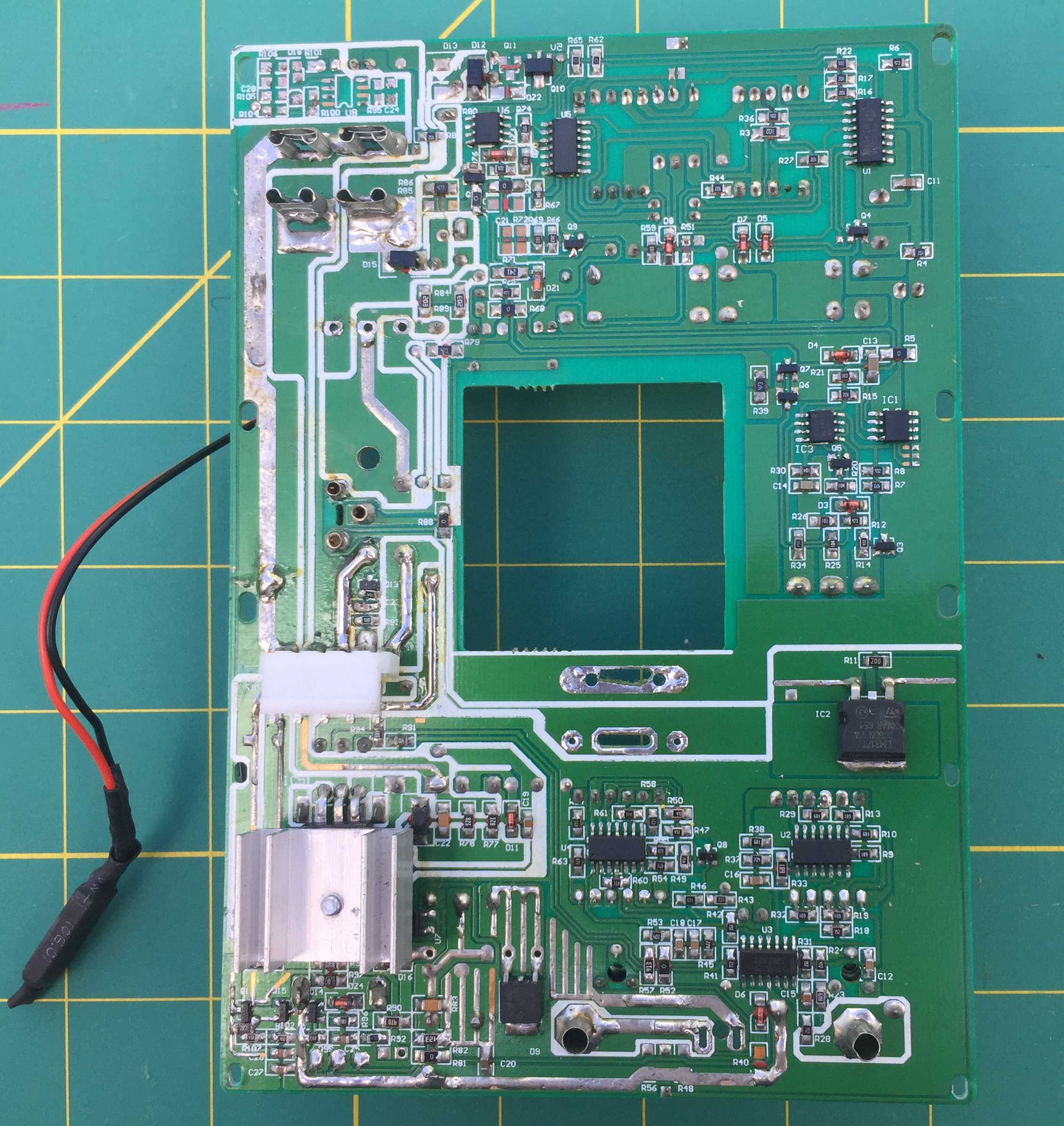
With the front panel separated the PCB can be inspected in detail. You will note that the built quality of the board is often poor. Solder flowed onto the SMD components and tinning of the larger PCB traces is often quite poor. This may be the most common cause for failures which I will describe later.

A triac can be replaced without fully removing the circuit board from the front panel. To do this cut off the leads right at the device and soldering the replacement to the stubs of the leads. But with the front panel removed it is not too much more effort to fully remove the PCB and replace the triac by properly desoldering it.
Note that if the unit’s mains fuse has blown catastrophically (heavily blackened glass tube) then it can generally be assumed that the triac has also blown, or at least been severely overloaded, so should be replaced.
Unfortunately it will then be found that just replacing the triac often does not fix a failed unit and the replaced component will blow again on test.
During triac replacement some forums have recommended adding a finned heatsink as the PCB only provides a small area of copper to cool the triac. Installing a finned radiator heatsink can be accomplished by attaching the replacement triac with heatsink at right angle to its original position on the PCB.
I though prefer to heatsink the replacement triac by wiring it on extended leads so that it can be relocated and bolted to the welder’s metal work because small finned radiators are not very effective inside a sealed enclosure. The triac used must be a fully insulated variety or a silicon pad used to insulate it when it is bolted to the chassis.
Also in my experience a triac blowing is generally not because of overheating, but a consequence of other faults.
To get full access to the components on the PCB for inspections and repair the PCB should be fully removed from the front panel.
To do this the knobs of the SET CURRENT and SOLDER potentiometers are first removed. They just pull off. The mounting nut of the SET CURRENT potentiometer should then be removed so the circular clear escutcheon can be removed.

Now go to the back of the front panel and remove the 3 self-tapping screws and fibre washers holding the PCB . The 2 wires to the IRON sockets can be desoldered from the PCB. Alternatively, if you have no plans to ever use the units soldering iron just cut the wires off. The PCB can now be pulled free from the front panel. If the circuit card does not easily release then the 4 spade terminals connecting to the POWER switches may be the problem. These spade terminals can be spread slightly to free them from the switch terminals. Once the board is removed the spade terminals should be squeezed back into shape to ensure good connections are made with the switch terminals on re-assembly. Various bits of the PULSE selection push buttons will fall off once the board is removed so retrieve them for re-assembly.


Circuit
The 709A welder’s circuit was reverse engineered by detailed inspection and probing of the PCB. Only the welding circuit was analysed. The soldering circuit was not investigated but it appears to just be a variable output DC switching supply. Note as there are 2 wires only going to the soldering iron socket there can be no tip temperature feedback. Therefore the iron temperature is not regulated and the solder temperature setting selected is only indicative. For quality soldering a dedicated temperature controlled soldering station should be used.
The welding circuit was traced sufficiently to gain understanding of how it worked so that repairs could be undertaken.
In usual Chinese manufacturing fashion the identification markings of the ICs have been erased from the devices. Therefore my circuit shows a number of devices with part number unknown. These devices’ function has been inferred from their surrounding circuitry.

My published schematic is not complete and there is no guarantee that it is correct, but with sufficient knowledge of electronics the information this schematic provides will be enough to successfully diagnose and repair many faults.
The labels (TP-V to TP-Z) shown on the schematic are test points found on the PCB. They had no identification so have been given nominal identities.
Further reverse engineering is underway and a more complete and correct schematic may eventually be published.
Circuit Operation
The welding control circuit is powered by a transformerless power supply. This is energised when WELDING is selected. Multiple SMD resistors drop the half wave rectified AC mains to DC on C6. The DC voltage is zener limited to around 12V and feeds a 3 terminal 5V linear regulator which powers the control circuity.
The blinking red LED is driven by a SCR relaxation oscillator. No actual purpose for this blinking can be determined.
The first amp of the dual Op-Amp IC5 provides a ramp synchronized with the zero crossings of the AC mains. This ramp voltage is compared with the SET CURRENT control setting. Once the ramp level exceeds that setting the second amp output goes high.
My explanation of IC3 and IC4 operation is purely hypothetical as the part numbers for these ICs could not be determined.
IC4 appears to be a triple latch. I could not find a common part that performs such a function but its operation is clear. Pushing a pulse number button causes the corresponding output LED to light and latch. Pressing the button again causes the output to turn off. The 3 latches can be turned on and off independently hence cumulative values of pulse numbers from 0 to 18 can be selected. The latch outputs are also inputs to IC3.
I believe IC3 is a microcontroller due to its complex functional. It takes in the weld initiation signal from the internal limit switch or the external foot pedal, the phase control turn-on point, the number of pulses selected, and outputs a signal to trigger the triac.
When a weld is initiated the phase control trigger point creates a gate trigger signal for the main triac at the appropriate point in the AC half cycle. C20 ensures the trigger signal is just a short pulse. By phase control the effective welding current can be varied. The number of pulses selected sets the number of half cycles the controlled current is present for. Because current flows for only part of a half cycle it is being called a pulse.
The value of the current is not actually regulated as the current flow depends on the resistance through the materials being welded, but by maintaining a pressure between the materials to be welded the currents, hence heating power for each weld, will be reasonably consistent. The pressure adjustment knob at the top of the unit sets a spring tension that opposes movement of the welding arms. By pressing the battery to be welded up against the welding arms until the arms move sufficiently to actuate the limit switch each weld will take place at a consistent pressure.
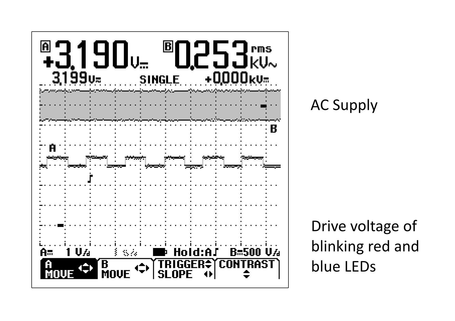
Various waveforms at key points of the circuit are shown below:-


Fault Finding
Having a schematic and knowing the expected operation of the various functional areas, systematic fault finding can take place.
Note you will be working on a live AC Mains circuit. Even the electronic common can be at a lethal AC potential. It is safest to use a mains isolation transformer to power the welder while fault finding.
The only connection that needs to be made to the PCB for testing is the AC power. To save energising the welding transformer or blowing a triac while initially fault finding the output wire to the power transformer (right most red wire of the power connector) can be disconnected by extracting it from the connector.
The unit has numbers of LEDs that come on or flash at various times during operation. Some provide no useful operational function and appear to have just been added to provide bling, but all can be useful to help in fault-finding.
On plugging in the AC power and turning on the WELDING power switch the red and blue LEDs at the top of the SET CURRENT knob escutcheon should be checked. The red blinks at around once a second while the blue is steady.
If no LEDs light there is obviously a control power problem to locate.
Due to poor quality of construction common faults noted are caused by dry joints or even resistors falling off the PCB! Components falling off appears due to poor reflow soldering or running very hot then coupled with the vibration each time the welding power transformer energises. This problem has been noted with the dropping resistors (R72, R73, R78, R79) of the power supply and the driving resistors (R68, R83) of the zero crossing detection transistor (Q19). If zero-crossing detection is not occurring reliably the triac may be triggered on randomly or for excessive time which will then blow the fuse and triac.
By triggering the welder by pushing up the welding arms the 2 red LEDs at the bottom of the CURRENT SET knob escutcheon should be seen to flash. The duration of the flash will vary dependant on the SET CURRENT and PULSE controls setting. The red blinking LED may also be noticed to extinguish for the duration of the pulse.
If the SET CURRENT adjustment appears to have no visible effect on the LEDs pulse the potentiometer itself could be faulty. Because it is mounted on an escutcheon that is not actual fixed to the front panel, the potentiometer body can twist when the knob is rotated to an end stop. This eventually causes the potentiometer to fail.
Once the lights are working as expected and the triac is known to be good then the power connector wire to the transformer can again be re-attached. With the transformer connected, on triggering the welder by pushing up the welding arms there will be a distinct audible clunk from the transformer even though no welding current is flowing.
The 2 white LEDs above the welding arm will also light whenever the transformer is energised.
Test welds can then be tried and hopefully everything will be normal and nothing will blow.
Note the unit’s name plate indicates the mains power fuse should be 20A but 15A is the highest rating that is readily available in the M205 package. A 15A fuse has been found sufficient.
Installing a lower rated fuse during testing is of no benefit when the transformer is in circuit. The fuse will invariably blow due to the high magnetization inrush current of the transformer. Also the type of fuse used has no chance of protecting the triac if there is still a fault.
If wishing to be cautious during final tests an external current limiting device such as a NTC thermistor can be used. Remember thermistors providing a soft turn-on function needs to cool down between operations to restore their current limiting resistance for subsequent operation.
Sunkko 788+
I also investigated a Sunkko 788+model, again only the welding circuit. This is an older model which has been superseded by the 788H. It was looked at for circuit comparison purposes but actual operation could not be checked as it previously had been cannibalised by someone.
Its circuit is obviously different to the 709A as it has a digital display and different interface for setting the number of pulses but I assume that the general principal of operation for both would be somewhat similar. Looking at the circuitry of the 2 models did give a few answers to questions I had about then 709A’s circuitry.
It is noted that the 788+ uses a physically smaller transformer compared with the 709A. This implied that its maximum welding current or duty cycle is less although their specification sheets do not indicate this clearly.
Externally the 788+ looks identical to the 788H although photos seen of the 788H internals show significant difference in the control circuit board layout. The specification sheet for the current 788H model versus the 709A also indicates a significant difference in weight. This is consistent with the smaller transformer of the 788+ that I investigated.
Reverse engineering was again made difficult by the erasure of part numbers on ICs.
Its circuitry confirmed a microcontroller is being used. U5 interfaces with U6 which is a 24C02 I2C memory so the 14 pin IC U5 has to be a micro.
This U5 and U6 combination as well as manage the interface pushbuttons and digital displays appear to provide the similar core functionality to IC3 in the 709A so confirmed that the 709A’s IC3 is also a micro.
I may eventually complete the reverse engineering of the 887+ circuitry but I would prefer to focus on the current 887H model if one becomes available.
This welder’s control circuit needs more power to operate because of its LED display . The dropper resistors for its transformerless power supply are 1W through hole components rather than SMDs. This suggests that to prevent re-occurrence of the resistor problems in the 709A it would be useful to replace any missing 1206 SMD resistor with 1/2 W leaded resistors. Many of those SMD resistors are running far too close to their 1/4 W rating.
Conclusions and Rants
My experience indicates that failed Sunkko 709A battery spot welders can be repaired, often with only a few components. All that is needed is knowledge, which I have gone some way towards providing in this blog.
Can the Sunkko circuitry be improved? I am sure it can but to improve something you first need to know how it was supposed to work.
Junking then dissing the product or totally modifying it is not the technical way to repair something.
Although many comments on the internet criticise Sunkko products, they have obviously sold in large numbers so many of them must be in use trouble free. They also effectively meet the market niche for
low cost battery spot welders for hobbyists or small commercial enterprises.
All commercial products will have some design problems that affects a varying number of the units manufactured. A company would not still be in business if all their products were lemons.
As Sunkko welders work successfully for a period and are still in manufacture they should be able to be restored to working condition again. With information and cost effective spare parts most products can be repaired. Unfortunately now days most Chinese and other manufacturers do not readily entertain providing such support.
